Deconstruction
Motor Re-Position
In order for the frame of the machine to support an additional gearbox, the chassis needed modification. The electric motor powering the system needed to be realigned in order for the power transmission to operate correctly. The motor is bolted to a support bracket which in turn is welded to the chassis frame. Due to the lack of welding equipment available the motor mounts needed to be bolted to the frame instead of welded.
 |  |  |
|---|---|---|
 |
Power Box Re-Position
To make room for the additional gearbox, the power box for the system required re positioned. Once the welds holding the power box to the chassis were cut off, the motors were re-routed to the outside of the frame. This allowed for the power box to be bolted to the outside of the frame and the motors to be re-positioned into their respective places.
 |  |  |
|---|---|---|
 |  |  |
 |
Cutting Angle Iron Supports
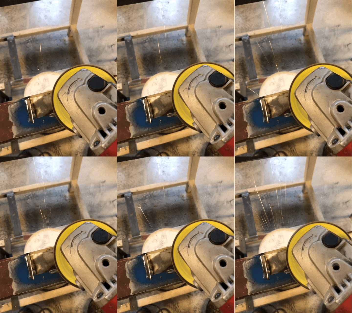
To securely fasten all the parts to the frame, angle iron was notched to fit precisely over the frame rails. The notches were initially cut using a band saw. Afterwards a bench grinder was used to bring the notches to their final dimensions. A square file was used to make the corner of the notch square.

Output Gears
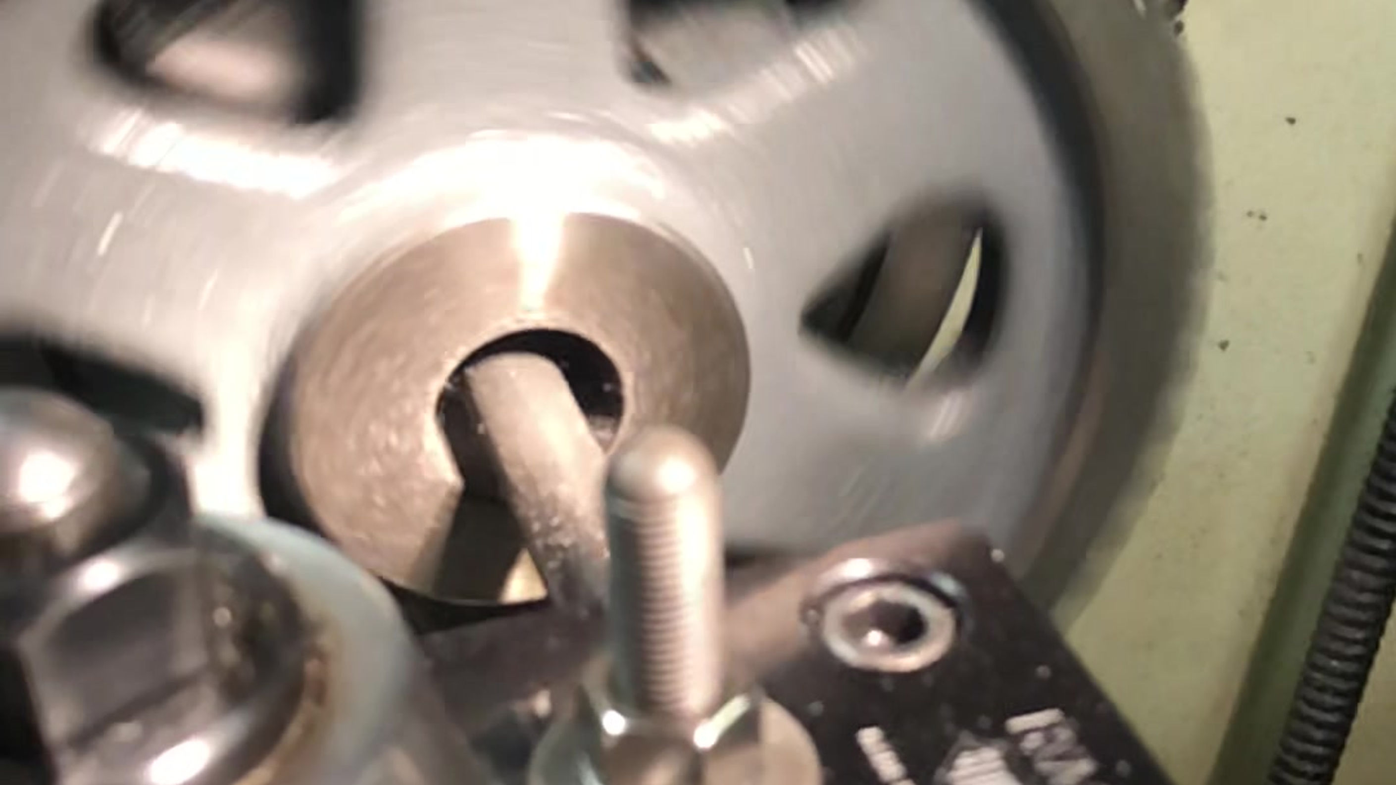
The gear size required for the device was not a nominal size. Custom gears were ordered and the inner diameter needed to be bored to the correct shaft size. Once the gears were bored to the correct dimension, they were broached to allow a keyed connection to the shaft.
 |  |  |
|---|

First Gearbox Alignment Spacers
The first gearbox needed to be elevated in order to have the output shaft concentric with the input shaft of the second gearbox. The spacers were made from block aluminum and drilled through allowing bolts to be used to secure the gearbox to the frame.
 |  |
|---|
Second Gearbox Bracket
An additional mounting bracket was constructed from 1/2 inch steel plate. The holes were drilled on a milling machine utilizing drill tables from CAD software.
 |  |  |
|---|
Bolted Connections
All component supports were drilled and bolted to the chassis of the machine.
 |  |
|---|
Motor to Gearbox 1 Chain Drive
ANSI 50 roller chain is used to connect the motor to the first gearbox. The chain needed to have 5 inches of links removed in order to properly secure and tension the drive.
 |  |  |
|---|---|---|
 |
Chain Guard
For safety precautions a guard was constructed to protect the operator when the machine is running. The upper guard was constructed from sheet metal and fastened to the frame and gearbox #1 bracket. The lower chassis was enclosed with 3/4 inch plywood on the exposed chain side.
 |  |  |
|---|---|---|
 |  |  |


